Important Links:
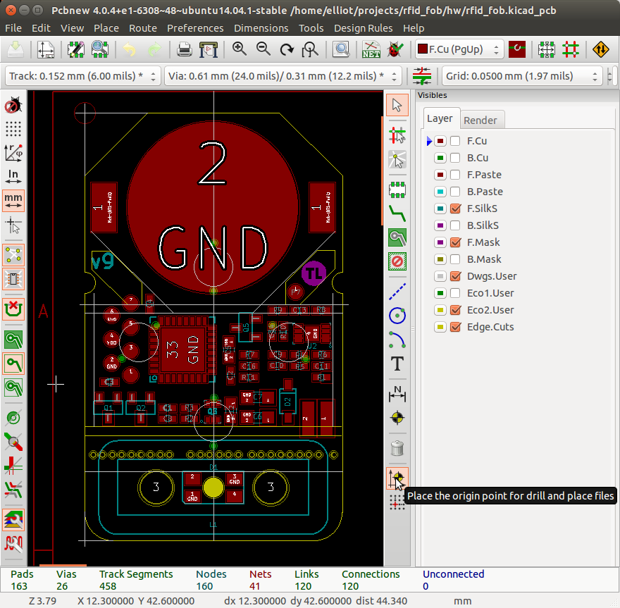
- Add auxiliary origin to top left of pcb. If your PCB isn’t rectangular (like mine) you can add reference lines to the Dwgs.User layer to find the top left corner.
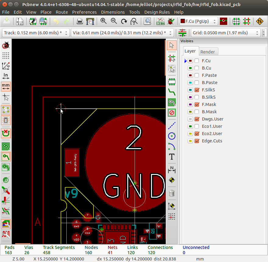
- Place cursor over new auxiliary origin and hit ‘spacebar’ to set relative coordinate reference. Notice how highlighted coordinates below are all zero.
- Hover crosshairs over center of each test pad and write down x/y coordinates (relative to auxiliary origin). After you’re finished you should have an array with the number of elements equal to number of test points.
// Test points
test_points = [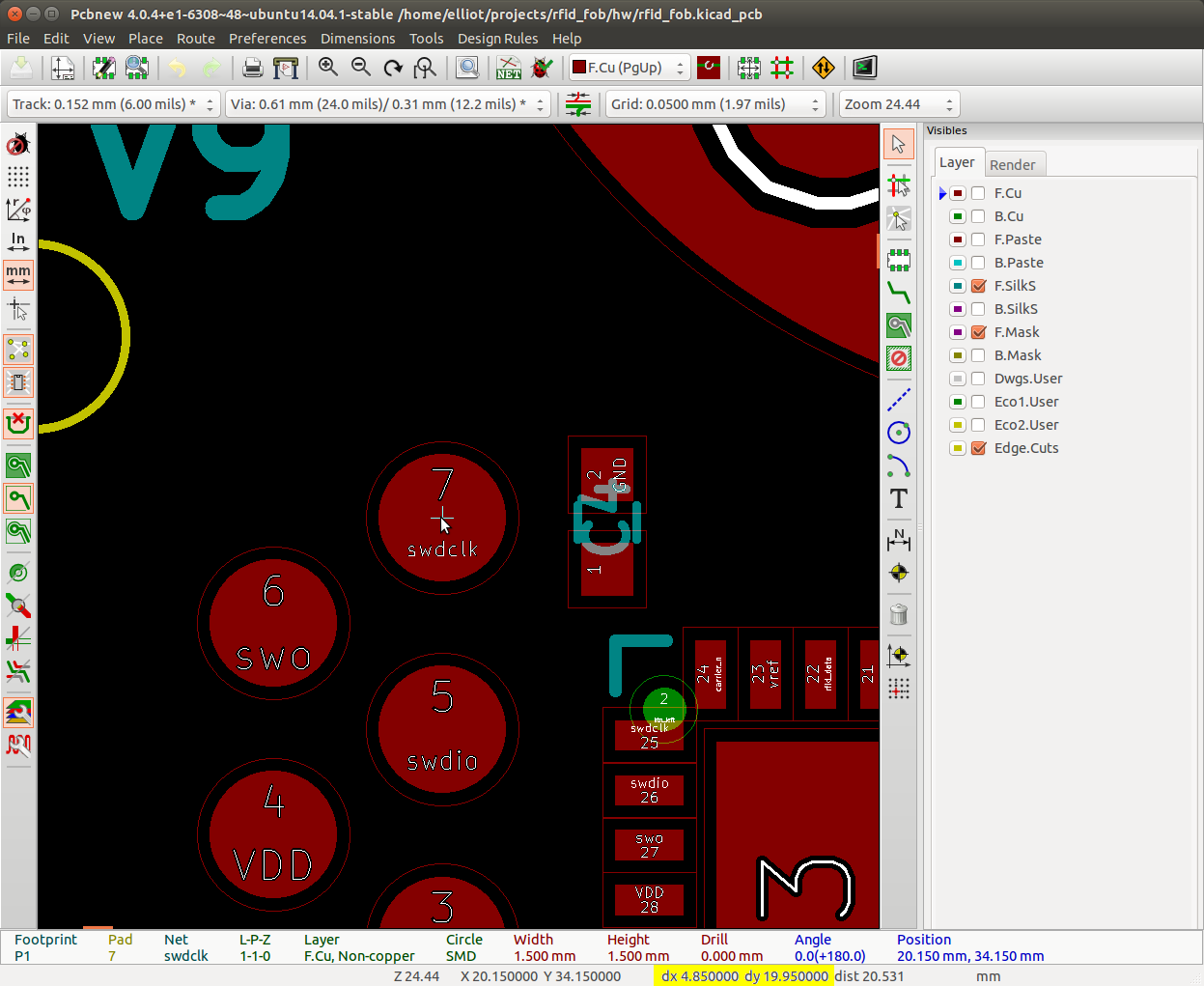
[4.85, 19.95],
[2.85, 21.25],
[4.85, 22.45],
[2.85, 23.7],
[4.85, 24.95],
[2.85, 26.2],
[4.85, 27.45],
[22.1, 18.8],
[23.4, 30.95],
];
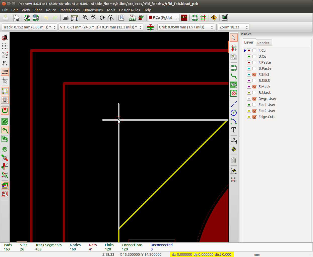
- Get max x/y dimensions of board. Use the same technique above to set relative referencing and measure max x and y dimensions. Write these down.
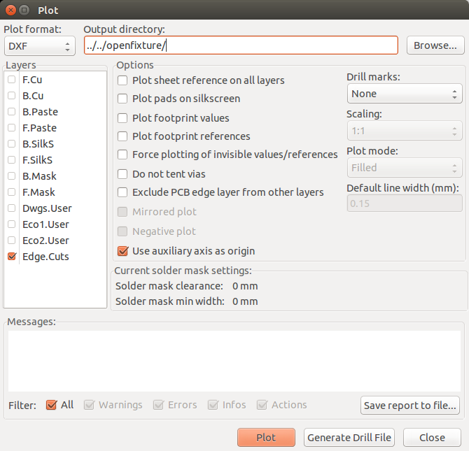
- Export board outline as DXF.
- Click File->Plot
- Make sure “Plot format” is DXF
- Set output directory to where ever the OpenFixture repo exists
- Under ‘layers’ only select Edge.Cuts
- Under ‘Options’ select “Use auxiliary axis as origin”
- Click ‘Plot’
- That’s it! Time to plug values into the OpenFixture parametric script.